Solved 14 A phototransistor is a lightsensitive Circuit Diagram
Solved 14 A phototransistor is a lightsensitive Circuit Diagram The more light that hits the photodiode, the more electrons flow into the base, and the stronger the current becomes. Phototransistor Circuit: Make an Automatic Light On/Off Switch. Now that you understand the basic concepts of a phototransistor, you can build an automatic switch that turns on a light when it's dark. The response curve of a phototransistor has a broad wavelength range, from the near-ultraviolet, visible, and near-infrared parts of the electromagnetic spectrum. Therefore, the phototransistor can be used in various light detection circuits and devices. A typical phototransistor. The phototransistor's wavelength spectrum is shown below. In this project, we will build the most basic phototransistor that is really possible. We will make it so that when light is shined on the phototransistor, such as from a flashlight, a buzzer will go off. So this circuit can act as a kind of light alarm circuit- if light is shone on the circuit, a buzzer will go off. Parts Needed. Phototransistor
Light Operated Relay using Phototransistor. When there is enough light falling on the phototransistor Q1, it turns ON and provides a base current to transistor Q2. As a result, Q2 is turned ON and the Relay is energized. Darkness Operated Relay using Phototransistor. With slight modifications to the Light Operated Relay Circuit, you can To make a basic light sensor, you need to know the key parts. Each part is important for the sensor to work well. You'll need phototransistors, resistors, and other stuff for putting the circuit together. Light levels can change how well the circuit works. The phototransistor can work in active or switch mode, depending on the light
Basics of Phototransistor Circuit Diagram
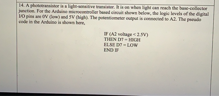
Arduino With Phototransistor. A Phototransistor is a semiconductor device that's basically an NPN/PNP transistor but it doesn't have a base terminal lead. Instead, the junction is exposed to ambient light that hits the base of the phototransistor which develops a small voltage across the BE junction causing the transistor to conduct (switch ON). A typical simulation model for an NPN phototransistor circuit is shown below. Typical simulation model for an NPN phototransistor circuit. Your goal in this circuit is to construct a load line so that you can determine the photon flux (i.e., base collector voltage and current) that will produce switching behavior and saturation. At low photon * A photodiode or phototransistor will also work. Connecting a Light Sensor to an Arduino. To connect a light sensor to an Arduino, connect the light sensor in series with a resistor between 5V and GND. Then connect the middle point between the resistor and light sensor to an analog input pin on the Arduino.