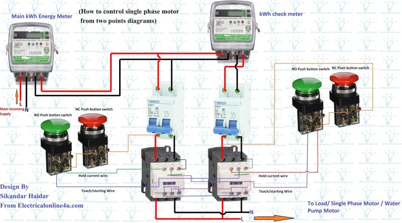
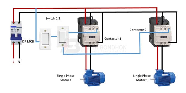
single phase motor control from two places Circuit Diagram
single phase motor control from two places Circuit Diagram Solved Design And Draw An Electrical Control Circuit Showing How Chegg Com. Two Wire Control Start Stop Jog Circuit. Three Phase Six Step Motor Control Circuit Diagram Composed Of Mc33035 Under Stepper Circuits 60609 Next Gr. Control Circuit To Interface Electric Power Steering Scientific Diagram.

BDC Motor Controller Circuit Design . A traditional BDC motor controller circuit is an H-bridge. This is an electronic circuit with four open/close switches that supply positive and negative voltage by turns. By closing high-side and low-side switches in a diagonal pattern, the motor rotates in one direction. A very common form of latch circuit is the simple "start-stop" relay circuit used for motor controls, whereby a pair of momentary-contact pushbutton switches control the operation of an electric motor. In this particular case, I show a low-voltage control circuit and a 3-phase, higher voltage motor: L1 L2 M1 M1 Start Stop M1 motor To 3
Automatic Sequential Motor Control Circuit Circuit Diagram
In this video, we demonstrate how to design and wire a motor control circuit using two timer relays. This method is useful for applications requiring delayed

A two-phase motor is a type of electric motor that consists of two separate windings, often referred to as the "main" and "auxiliary" windings. two sets of windings are used to create a rotating magnetic field. the power supply, the motor, and the control circuit. The power supply delivers the required voltage to the motor I am looking for a circuit design for a motor control for a 110v outlet. The power is activated by a microswitch. This would be for a 2 hp motor dust collector. Because 50 amp is huge a 3 phase motor will work better than a single phase system. Moreover it also includes a reverse forward facility and it works with sensorless motors.
2 Simple Bidirectional Motor Controller Circuits Explored Circuit Diagram
Some times we require less RPM (Rotation Per Minute)of motor and some times we require very high RPM of motor.So today I am going to make a circuit using IRFZ44N MOSFET that will control the RPM of motor.We can use this circuit upto 15V DC power supply. This circuit require only Z44N MOSFET and a variable resistance. Let's get started, Working of Sequential Motor Control Circuit. The working of a sequential motor control circuit is relatively simple. The control circuit first activates the first motor in the sequence by sending a signal to the associated starter, contactor and relay.Once the relay receives the signal, it switches on the power to the motor, causing it to start running.
