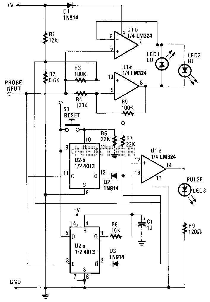
probe under Logic Circuits Circuit Diagram
probe under Logic Circuits Circuit Diagram Input Test Circuit. This project will utilize an input test circuit consisting of several resistors and two switches. This test circuit will be used to test and demonstrate each logic gate. Below are both the schematic for the test circuit and picture of the breadboard. It will provide voltage outputs that represent logic levels 0 and 1.
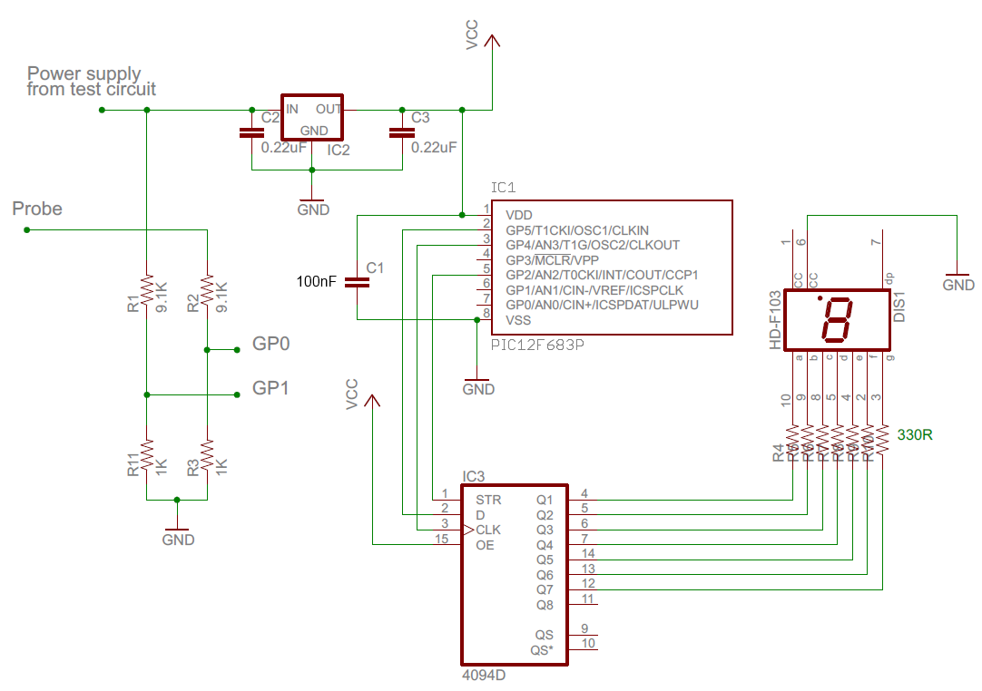
For the probe to function correctly, the ground on the logic probe and the ground on the circuit under test must be connected. This is where the 0V ref pad comes into play. This pad gives you a place to connect your probe's ground to the ground of the circuit under test. Enclosure Logisim is an educational tool for designing and simulating digital logic circuits. With its simple toolbar interface and simulation of circuits as they are built, it is simple enough to facilitate learning the most basic concepts related to logic circuits. allowing you to build up and test huge circuits; this step-by-step process just
Digital Logic Projects: Simple Ideas for Beginners to Build Their Own ... Circuit Diagram
The basic steps in modeling and analysis of a digital logic circuit are: 1. Open . Multisim. and create a "design" . 2. Draw a schematic diagram of the circuit (components and interconnections). 3. Design digital test patterns to b e applied to the circuit inputs to stimulate the circuit and Build and simulate circuits right in your browser. Design with our easy-to-use schematic editor. Analog & digital circuit simulations in seconds. Professional schematic PDFs, wiring diagrams, and plots. No installation required! Launch it instantly with one click. Launch CircuitLab or watch a quick demo video → The traffic light controller is a more advanced project that involves creating a digital logic circuit to control the timing of traffic lights. You can use a microcontroller or a programmable logic device (PLD) to create the circuit. This project is a great way to learn about state machines, counters, and timing circuits.
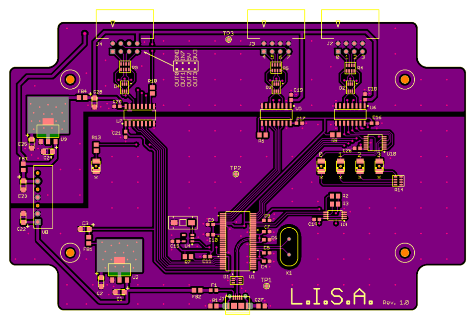
Often, it's best to remove the potentially damaged chip from the build and test it independently from the other components in the electronics design. This article discusses a simple Arduino-based logic IC tester you can employ to find problems in your digital circuits. This image shows the completed build. BOM. Part/Quantity Overall, these basic digital logic projects are a great way to get started with digital electronics. They are easy to build and can be used as a foundation for more complex circuits. With a little bit of practice, you can create your own digital logic circuits and start exploring the world of electronics. Advanced Digital Logic Projects