PDF Teaching Digital Logic Circuit Design via Experiment Circuit Diagram
PDF Teaching Digital Logic Circuit Design via Experiment Circuit Diagram It involves using logic gates and combinational and sequential circuits to create complex digital systems that can perform a variety of tasks. What are the prerequisites for learning digital electronics and logic design? A basic understanding of electrical circuits and fundamental concepts in electronics is recommended. Familiarity with binary

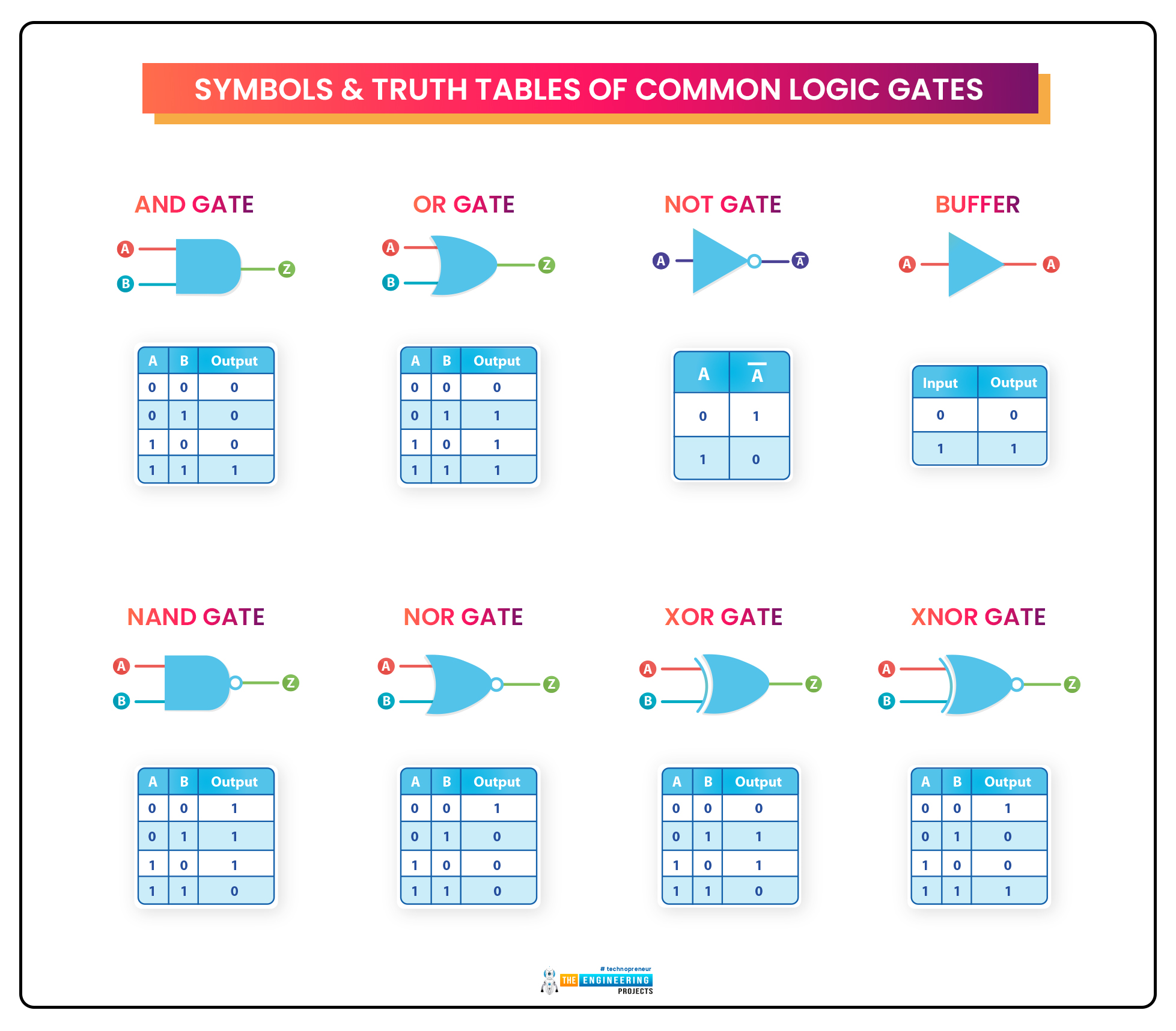
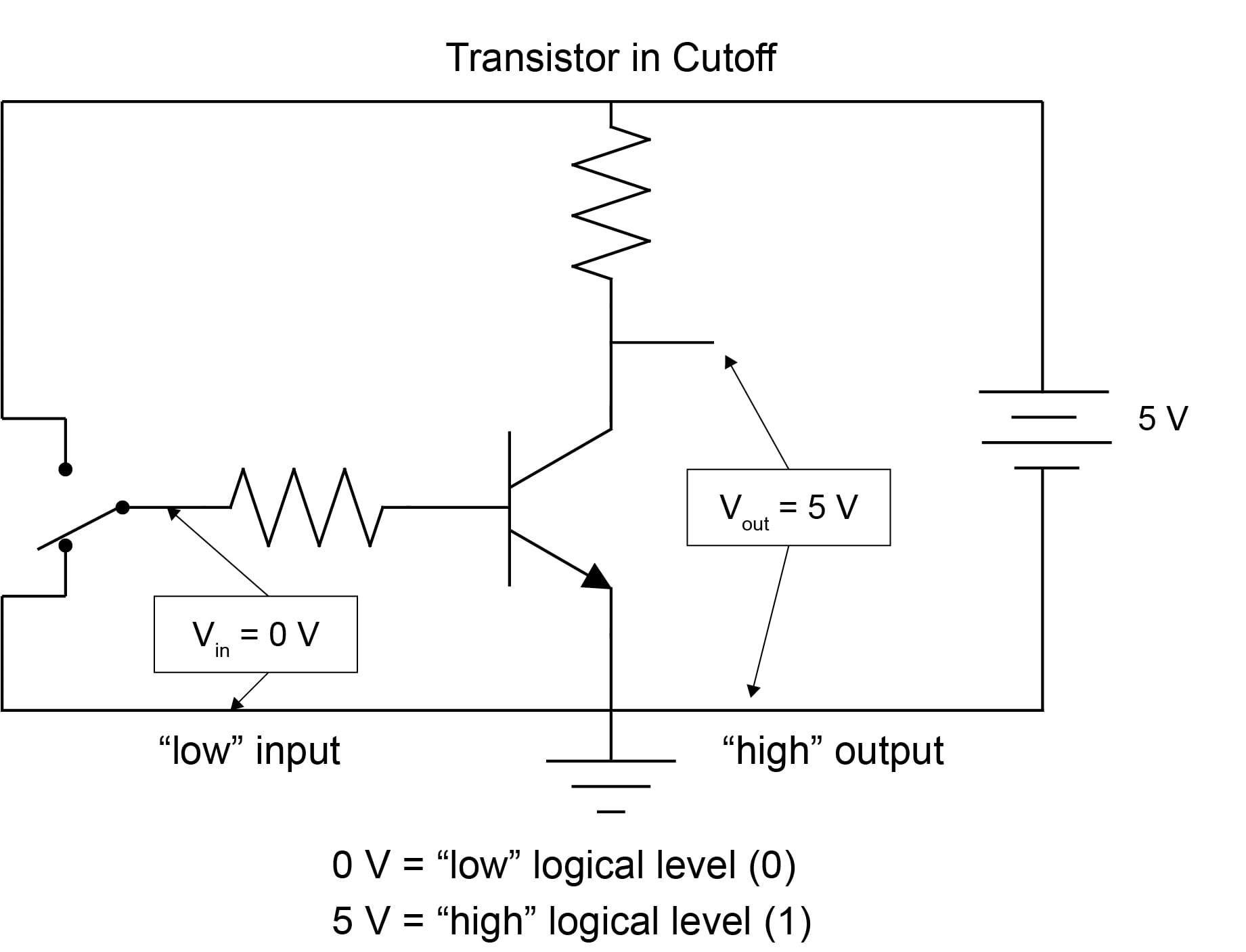
Most digital logic gates and digital logic systems use "Positive logic", in which a logic level "0" or "LOW" is represented by a zero voltage, 0v or ground and a logic level "1" or "HIGH" is represented by a higher voltage such as +5 volts, with the switching from one voltage level to the other, from either a logic level "0" to a "1" or a "1" to a "0" being

Types, Functions and Applications Circuit Diagram
Combinational circuits are built of five basic logic gates: AND gate - output is 1 if BOTH inputs are 1; Digital logic circuits are usually represented using these six symbols; inputs are on the left and outputs are to the right. When a computer's "speed" is cited, this is the value in question. It is possible to design "asynchronous 4.1.1. Logic Gates with Multiple Inputs¶. Assume we design a digital circuit and need a NAND gate with 3 inputs. We may assemble the 3-input NAND gate using 2-input NAND gates and an inverter as building blocks, see Figure 4.1.Using Boolean algebra, it is straightforward to show that this circuit implements the logic function \(Y = \overline{A\,B\,C}.\)
Introduction to Digital Logic Design CSE 140: Components and Design Techniques for Digital Systems . Winter 2016 . three basic 'logic' operations: 1. Intersection: AND (2- input); Operator: . 2. Union: OR (2-input); Operator: + circuit it represents by cascading gates (and vice versa) Next class • Designing Combinational circuits

A Comprehensive Guide to Digital Logic Gates Circuit Diagram
Simple Logic Gates and Circuits: Logic gates are some of the basic building blocks of digital logic circuitry. In this Instructable we will talk about a few of the simplest of these devices, and see some of the fun things you can do with them. Here we outline two simple ways to design a logic circuit that results in the exact truth table we