Object Detection Demo Circuit Diagram
Object Detection Demo Circuit Diagram The basic Arduino boards are not powerful enough for image processing. Heck, they are not even good enough to capture photos without the help of a desktop computer. However, there is a special imaging device you can use to make an Arduino detect objects. The special device I am referring to is the Pixy camera.This camera incorporates a microprocessor which does all the heavy image processing This sensor can detect objects from 2 cm to 400 cm, or roughly, 1 inch to 13 feet. The sensing angle is 15 degrees or less. Its operating voltage is 5 volts. The pins of the HC-SR04 are VCC, TRIG, ECHO, and GND. The VCC pin connects to the 5V pin of the Arduino, GND connects to the GND pin.

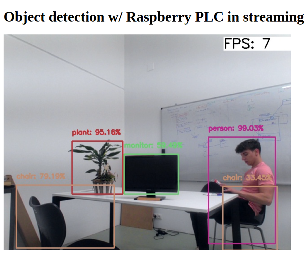
In this project, we will build an object detection system using the HC-SR04 ultrasonic sensor and an Arduino Uno. The system has a variety of practical uses, such as preventing theft, monitoring areas to detect pets or rodents, and much more. Features: LCD Module: Displays messages as an object or intruder approaches. The webcam_object_detection.py script captures video from your webcam and performs object detection using a custom YOLOv5 model. Detected objects are labeled and displayed on the screen in real-time. Real-time Object Detection with Arduino Integration The webcam_object_detection_with_arduino.py

How to Make an IR Object Sensor With Arduino Circuit Diagram
From the Arduino board connect the output (pin 7) to the +ve terminal of the LED. Connect -ve terminal of the LED to ground; Write the code in Arduino UNO software and run the program. Move the object in front of the IR module and see the LED turning ON which indicates the presence of the object. Working of object detection: #Ultrasonic Sensor is used for the precise detection of objects. The ultrasonic transceivers, that are the #transmitters and #receivers, use the concept of converting electrical energy into ultrasonic sound. The ultrasonic sensor emits sound waves at a frequency above human hearing and calculates the distance of any object or obstacle in its path. The distance is calculated by counting the
To demonstrate the capability of an IR proximity sensor, we'll be using the HW-201 IR obstacle sensor module. The detection range of this module is from 2-30cm (depending on the surface). It only has a digital output, which means, it only gives a HIGH or LOW signal, or 1 or 0. HIGH if it detects an object, LOW if no object is detected. Follow the schematic to make the circuit. Here, the voltage produced by the IR Receiver is converted from analog to digital and is used as a reference to know whether the object is detected or not. This pic can be called as the signal pin. An LED is used to indicate the detection of the object.