High Power IR Infrared Transmitter Circuit Diagram
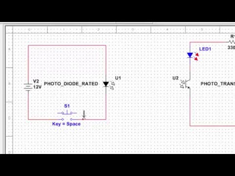
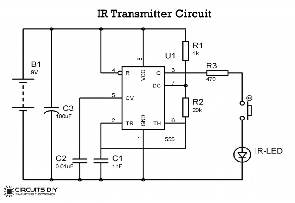
High Power IR Infrared Transmitter Circuit Diagram The infrared rays emitted by the IR Transmitter i.e. IR LED must be detected by the IR Receiver i.e. TSOP 1738. In the transmitter part, the 555 Timer is designed to operate in Astable Mode. Hence, it generates a continuous pulse and the frequency of the pulse is 38 KHz.

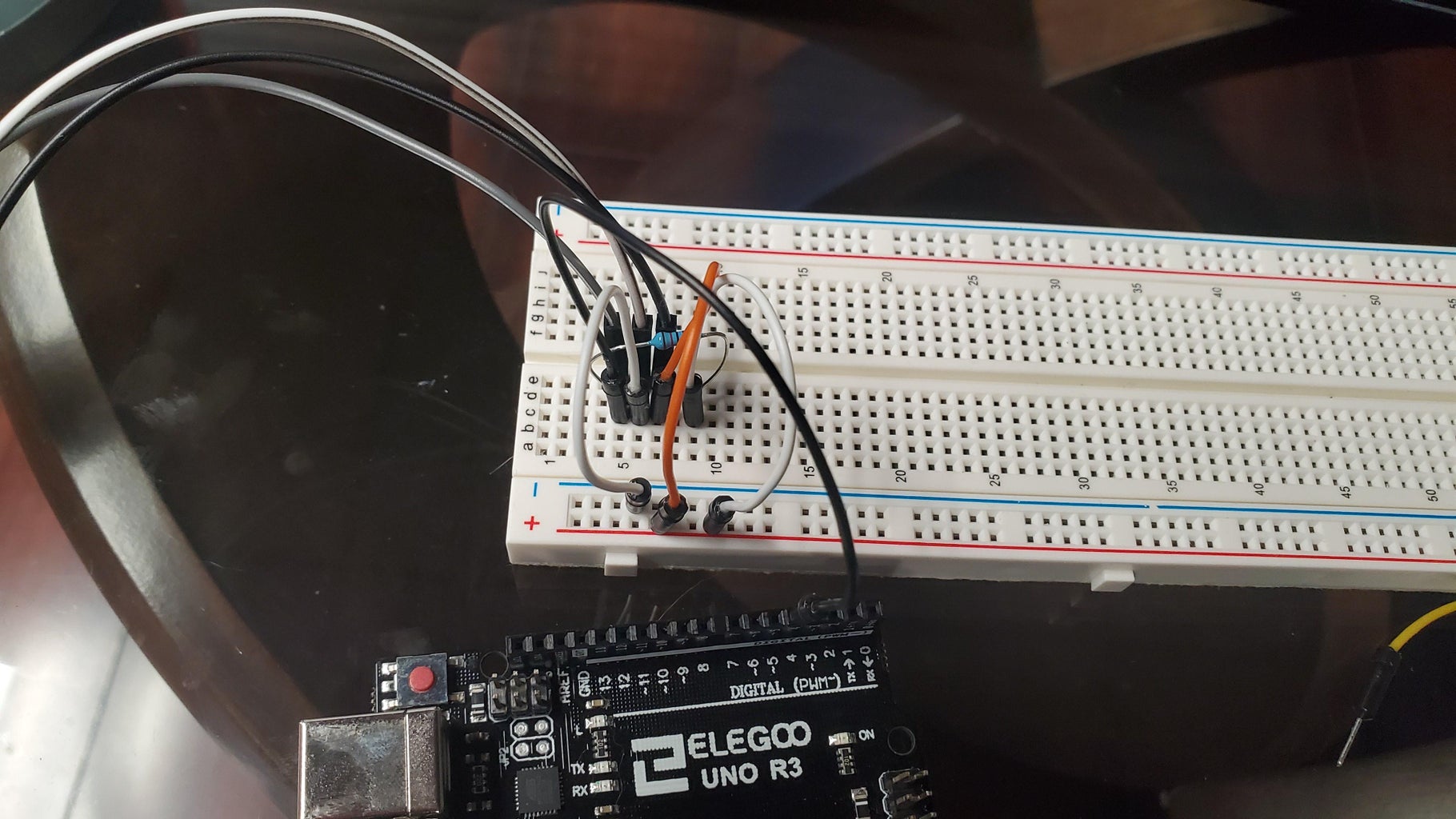
With a simple IR transmitter and receiver, you can make remote controlled robots, distance sensors, heart rate monitors, DSLR camera remote controls, TV remote controls, and lots more. The example circuit has the IR receiver connected to the Arduino, with a red LED connected to pin 10 and a green LED connected to pin 11: The presented simple infrared transmitter circuit design can be used in the form of an infrared remote control, with a frequency modulated tone, to operate a to operate a complementing IR receiver circuit. How the Circuit Functions. The transmitting frequency is determined by C1 and adjusted using the trimpot 100k.
IR Transmitter and Receiver Circuits Circuit Diagram
Test Your Arduino IR Transmitter. After uploading the code to your Arduino, press each button and check the Serial Monitor. You should see "Nothing to send" until a button is pressed, at which point the corresponding IR code will be sent. Make sure you point the IR LED toward the device you want to control. Troubleshooting Tips: Simple infrared receiver. This is a simple infrared receiver for the burglar alarm system or the other protection, etc. It has a few components. There are the most common transistors and photodiode to receive an infrared signal( with an Infrared transmitter using 555). Let's build the Infrared receiver circuits. Which we have many circuits.
This topic shows how to make a simple infrared (IR) remote control system using the microcontroller PIC12F1822. This IR system has two circuits as known: IR transmitter circuit and IR receiver circuit. Both circuit based on the same microcontroller type which is PIC12F1822. This IR system uses NEC communication protocol.
How to Set Up an IR Remote and Receiver on an Arduino Circuit Diagram
The IR Receiver The IR receiver used was a 38 kHz infrared receiver module from RadioShack, but just about any will work just a well. This receiver was chosen so that it would reject all other frequencies, but the 38 kHz, including visible light. The 555 Timer The main idea to understand is the 555 timer is in a-stable configuration. An IR transmitter and receiver pair form a simple circuit. This project explains the principle of IR communication. The 555 Timer IC operates in an astable mode. It generates continuous pulses of the frequency. As the switch is pressed, the connection between an IR LED and the 555 timer IC closes. Then the IR LED emits light of some frequency.
