ESP32 Raspberry Pi Home Assistant Circuit Diagram
ESP32 Raspberry Pi Home Assistant Circuit Diagram Here is a list of the items which you need in order to complete this project. The LCD screen is optional, it is obviously useful if you plan on permanently installing or using your energy meter however you can just make use of the Arduino serial interface to display the information. An Arduino (Uno used here)- Buy Here
I was wondering if it's possible to interface an Arduino with a digital energy meter (used by utility companies) to fetch real-time energy usage data. Here's what I'm considering: Using an Arduino Uno or ESP8266 for the setup. Reading data through an optical sensor or pulse outputs (depending on the meter).

Simple Arduino Home Energy Meter Circuit Diagram
Monitor your energy consumption through the Arduino IoT Cloud using a MKR WiFi 1010, a MKR 485 Shield and a Modbus compatible energy meter. Arduino IoT Based Energy Meter Nov 11, 2022 At the core of the Smart Home Energy Management System is the Arduino UNO R4, which serves as the brain and central hub of this sophisticated energy management solution. The Arduino UNO R4 manages cloud connectivity through Arduino Cloud, allowing it to continuously track and report critical metrics such as battery percentage and historical As energy prices rise and environmental concerns grow, understanding and managing home energy consumption has become more important than ever. Enter the Home Energy Monitoring System . With the help of an Arduino board, you can create a system to monitor energy usage, identify wastage, and save money—all while contributing to a greener planet.
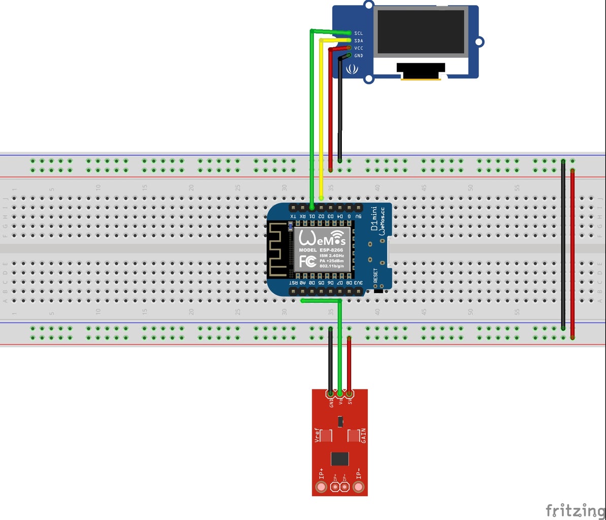
All the results can be visualized in the serial monitor or by using a LCD. I used a 16x2 character LCD to display all the results obtained in the previous steps.For schematics see the bread board circuit shown above. Connect LCD with ARDUINO as given bellow : LCD -> Arduino 1. VSS -> Arduino GND 2. VDD -> Arduino +5v 3.
DIY Real Energy Meter With Arduino and ESP8266 Circuit Diagram
In this tutorial, we will show you how to create an energy meter which allows you to track your energy consumption through the Arduino IoT Cloud. Regardless of whether you want to save energy, automate your home accordingly or simply become more aware of your consumption, measuring your electricity consumption is a good idea.
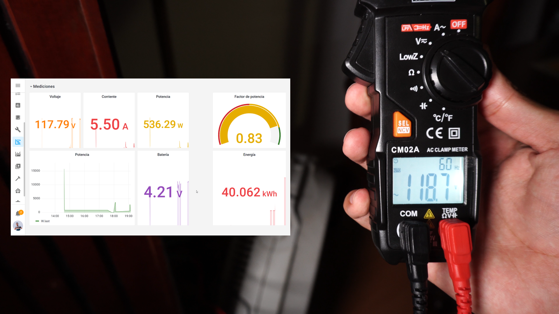
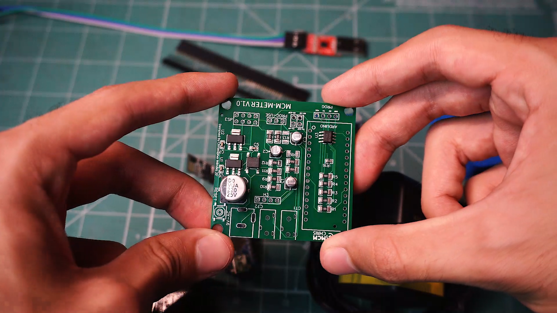
First a quick look at the installed setup: The Display. The display unit consisting of 4 large green led 7 segments. On the right is a 6 mode - mode chooser so that you can select by turning the potentiometer (bottom - right) whether the display shows real power, apparent power, power factor, RMS Voltage, RMS Current, frequency or cumulative kWh used. Before turning on the device, change the prog-use jumper to use mode. The board is powered by the micro usb arduino connector. (connect it to a 5v usb adapter). The board will automaticaly generate a Wifi network called ESP#####, click on it, and a WiFi manager will appear.