DIY Self Balancing Robot Circuit Diagram
DIY Self Balancing Robot Circuit Diagram Self Balancing Robot is a two-wheeler automated robot that can balance itself from falling to the ground. This is similar to other typical two-wheeled self balancing robots, such as the Segway. Its function is to maintain balance using the motor's axis movement of the wheels and body. Types of self-balancing robots. There are several types of Self Balancing Robot Using Arduino: Self balancing robot is an example of arduino project. A balancing robot comes under the category of autonomous project, where the robot tries to balance itself by using the gyroscope sensor MPU 6050. You can make the circuit at your home by using vero board or you can directly order a PCB from any PCB Circuit Diagram. Making the connections for this Arduino based Self balancing Robot is pretty simple. We just have to interface the MPU6050 with Arduino and connect the motors though the Motor driver module. The whole set-up is powered by the 7.4V li-ion battery. The circuit diagram for the same is shown below.
Now, at this stage, you should install the Arduino IDE on your Windows, Linux, or Mac computer.. Return to Table of Contents. Test the Motors. Let's test the motors to make sure they work. Plug the Arduino into the USB port of your computer using the USB cord. After being inspired by RYNO motors and other self balancing scooters from Segway, I always wanted to build something my own Arduino Segway Robot.Thinking for while, I decided to build a Self Balancing Robot using Arduino.This way I would be able to grasp the underlying concept behind all these scooters and also learn how PID algorithm works.. Once I started building, I realized that this bot Materials to make self balancing robot using Arduino. Arduino Uno you can also use Arduio nano too, but some changes in connections and codes need to be made CIRCUIT DIAGRAM for self balancing robot. Circuit for making self balancing robot. Making Connections with Arduino uno. MPU 6050 ( connection to analog pins in arduino)
Balancing Robot From Scratch Circuit Diagram
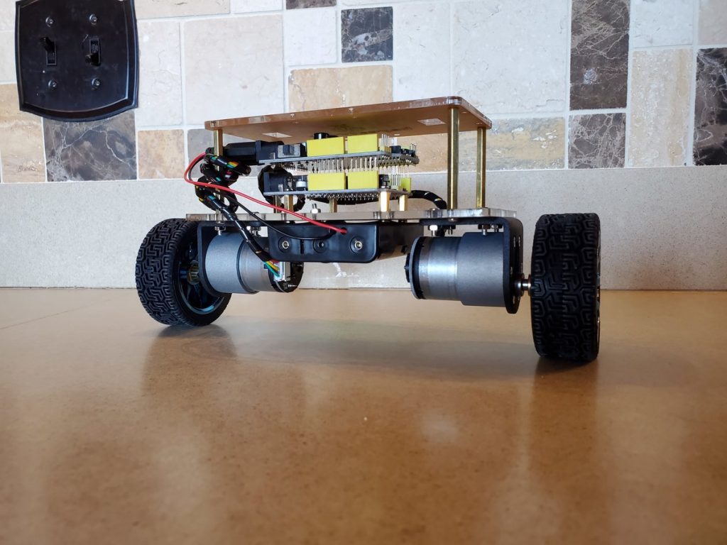
1. The physical structure of the robot is modified, so that the robot is much more robust and easier to control. The very early version is shown in the first picture, while the current version (2.0) is shown in the second picture. 2. An illustration of torque equilibrium of the robot is added. 3. A new program is written for PID tuning.

The self-balancing robot is similar to an upside down pendulum. Unlike a normal pendulum which keeps on swinging once given a nudge, this inverted pendulum cannot stay balanced on its own. It will simply fall over. This was due to the noise generated from the motor circuit acting upon the controller and the IMU. This was effectively
