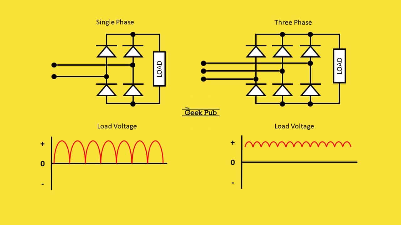
Bridge Rectifier Circuit Circuit Diagram
Bridge Rectifier Circuit Circuit Diagram Learn how to convert AC voltage into pulsating DC voltage using four diodes in a bridge configuration. See the full wave rectifier circuit diagram, output waveform, and how to add smoothing capacitors.
Learn how a bridge rectifier converts AC into DC using four diodes and a load resistor. See the diagram, the working principle, and the characteristics of this full wave rectifier circuit.

Bridge Rectifier Circuit Diagram And Waveform
Learn how to use four diodes to convert AC to DC with a diode bridge rectifier circuit. See the diagram, how it works, and what it's used for in power supplies and other circuits. A bridge rectifier diagram is similar, to a representation that illustrates the arrangement of components within a specific circuit. Its purpose is to convert alternating AC which is characterized by wave patterns into direct current (DC) that provides a consistent flow of electricity. Learn how to convert AC to DC using a bridge rectifier, a circuit made of four diodes arranged in a bridge configuration. See the circuit diagram, waveform, and operation of a bridge rectifier and its applications in various electronic systems.

Learn how to convert AC to DC using a bridge rectifier, a type of full-wave rectifier with four diodes in a bridge circuit. See the diagram, waveforms, characteristics, efficiency, advantages and disadvantages of bridge rectifier.
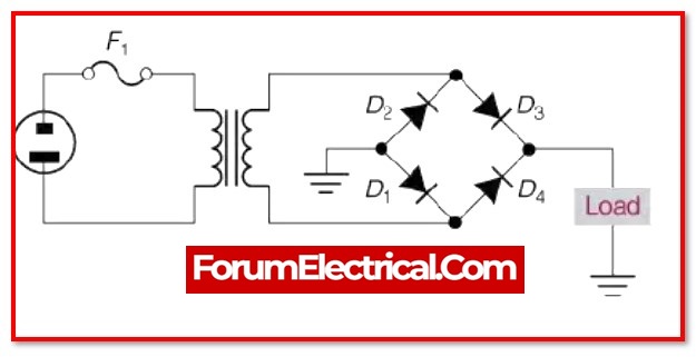
Diode Bridge: Four Diodes That Convert From AC to DC Circuit Diagram
Learn how to convert AC voltage into DC voltage using four diodes in a bridge configuration. See the circuit diagram, waveforms, formula, advantages, and disadvantages of full wave bridge rectifier. Learn how to convert AC to DC using a bridge rectifier circuit with four diodes and a transformer. Find out the advantages, disadvantages, and types of bridge rectifiers and their applications in electronic power supplies.