Audio Noise Reduction Using Low Pass Filters Circuit Diagram
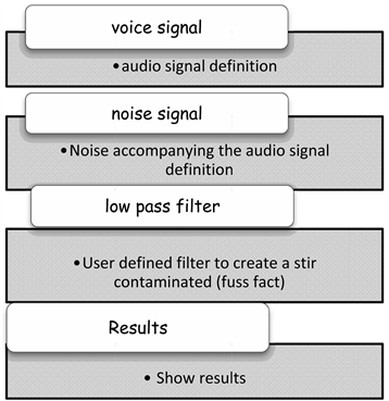
Audio Noise Reduction Using Low Pass Filters Circuit Diagram With the power spectrum displayed, we can choose a frequency range to pass, and apply a low pass filter. As the name implies, the low pass filter passes low frequencies (frequencies to the left of the cursor), and filter out high frequency "noise" (frequencies to the right of the cursor).
The low pass filter is not what you want, you want to compare your voltage to some threshold (e.g. 2.5 V) and decide whether it's high or low. A comparator does that. Your low-pass filter is still a very good idea, because it still removes noise, and especially at the point where the signal crosses the threshold voltage, you don't want it

Noise Removal using Lowpass Digital Butterworth Filter in Scipy ... Circuit Diagram
Basics : Band Pass Filters. The four common filters. Low-pass filter, passes signals with a frequency lower than a certain cutoff frequency and attenuates signals with frequencies higher than the pass filter is used to remove low frequency noise and preserves the high pas components. A bandpass filter is used to allow only a range of frequencies by taking human threshold voice. In this paper, we are using a low pass IIR (Infinite Impulse Response) and FIR (Finite Impulse Response) filter to remove noise from an audio signal.
Low pass filters have a wide range of applications in various fields such as audio processing, communication systems, and image processing. Audio Processing. In audio processing, low pass filters are used to remove high-frequency noise and unwanted harmonics. They can also be used to enhance the bass in music, making it sound richer and fuller.

Digital Signals for Dumb*sses (Part 6: How to Remove ... Circuit Diagram
If the signal occupies low frequencies and the main noise occupies high frequencies, then by using a low pass filter you can remove most of the noise.
To remove unwanted signals/noise we use filters of different types and specifications. Generally in the industry we need to choose the best fit by testing it with the signal to pinpoint the best filter to be used for removing the noise in a given use case. In this article, we are going to discuss how to design a Digital Low Pass Butterworth
How to Clean Up Noisy Sensor Data With a Moving Average Filter Circuit Diagram
The purpose of a low pass filter is to remove or reduce high-frequency noise or unwanted signals from a desired signal. It is commonly used in audio systems, communications, signal processing, and image processing . By eliminating high-frequency noise, a low pass filter enhances the clarity and quality of the desired signal. How It Works

If you want to get only signals of the human voice (85-300 Hz) from an audio recording, you might use a band-pass filter; If you need to remove electrical noise from an electrocardiogram (which It is a simplified form of a low-pass filter. Running a signal through this filter will remove higher frequency information from the output. While a traditional low pass filter can be efficiently used to focus on a desired signal frequency, the moving average filter is a more direct approach to simply "smoothing out" a signal.
